|


| |
Optical Image Correlating Velocimeter for
metallurgical plants
Optical Image Correlating Velocimeter (ICV) was developed to measure
speed and length of product in metallurgical process. The ICV represents alternative
solution to laser doppler based instruments achieving similar accuracy on good quality
surfaces and superior accuracy on rough and poor quality surfaces. For detailed
description of principle of operation refer to paper [1]. The
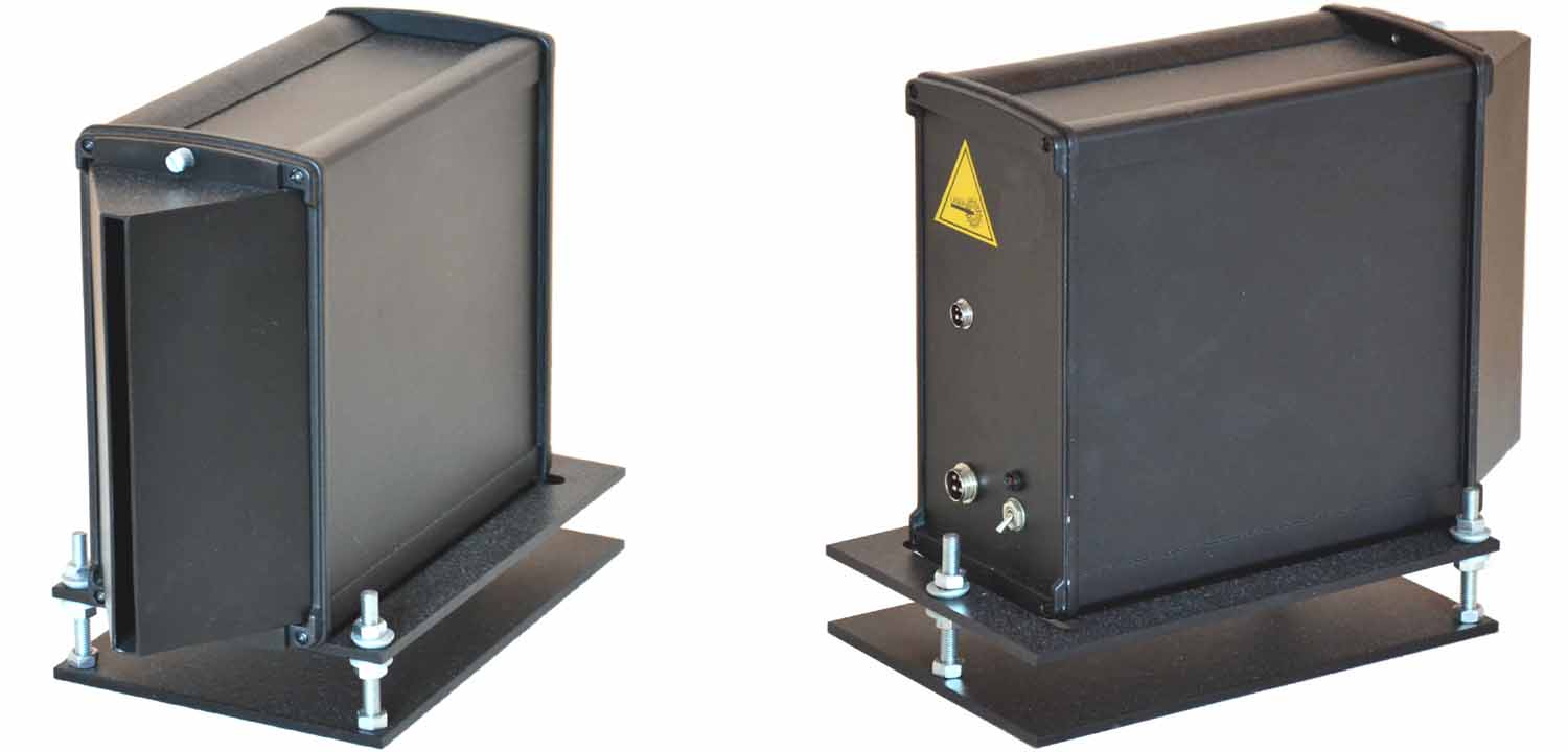
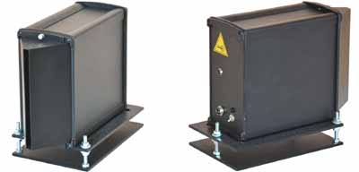
production model of the ICV is shown in Fig.1.
|
Fig.1.Image Correlating Velocimeter |
Basic Characteristic of the ICV
No contact measurement of speed , length, and distance to the product
Small size and weight
Wide range of stand-off distance
Mesure distance to object
Works well from very slow to medium range of product velocity
Instantaneous measurement of speed and displacement of the product
Wide operating temperature range
Quick and easy installation and service
Speed and length measurement of slab in
continuous casting process using ICV
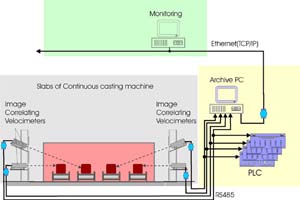
The ICV has been installed on quad continuous caster machine, connected
to MNLZ process control system, and operated flawlessly over 9 month period. Figure 2
shows installation diagram and four ICVs monitoring quad caster machine. The point of
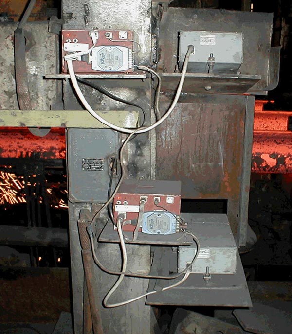
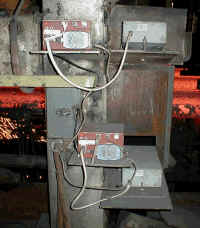
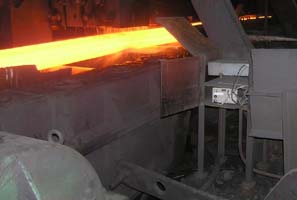
installation was close to the slab cutting machine. Figure 3 shows photograph of two ICVs
monitoring first and second slab on the quad caster. ICV at the bottom is pointed at the
first slab, which is 1800mm away, while upper instrument monitors the second slab 3700 mm
away. At this distance both ICVs operated without need for cooling. All four ICVs were
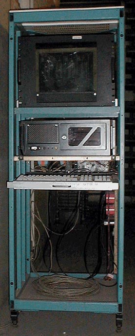
connected to process control and monitor computer, which processed and recorded data. Data
from the ICV can be also used to control operation of slab cutting machine. Important
feature of ICV is instantaneous reading of slab velocity and possibility to detect fast
and sudden changes in slab speed caused by instability in the crystallizer. Test results
of pilot installation and operation of the ICV were published in papers[3] and [4].
|
Fig.2. Installation diagram of four ICVs
on quad casting machine |
|
|
Fig3. ICVs monitoring
slab 1 and 2 |
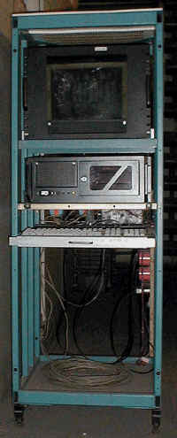
Fig.4. Computer rack |
Definition of measurements and data format
Instantaneous velocity: slab movement speed in mm/sec
Length: slab length in mm measured from the moment of entering the
ICV field of view or from the moment of starting new measurement
Distance: distance in mm from the reference point on the ICV to the
slab surface
Technical specification of process control system MNLZ for
continuous caster machine
- Slab temperature: 450...1100°С
- Slab velocity: -5...+5 m/min
- Velocity measurement accuracy: 1 %
- Length measurement accuracy: 0.15 %
- Stand-off distance:1600...4000 mm
- Depth of field: 600 mm
- Distance measurement accuracy: 0.2 %
- Output data rate: 8…16 Hz
- Digital data interface : RS485
- Operating ambient temperature range: -10...+60°С
- Enclosure environmental rating : IP-54
- External cooling: N/A
- Supply voltage: 220 VAC or 24 VDC
ICV controlling billet cutting machine
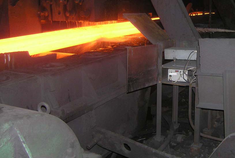
Figure 5 show ICV installed 2100 mm from the billet surface and
controlling cutting machine.
|
Fig.5 ICV controlling billet cutting
machine |
Technical specification of billet cutting system
- Billet temperature range: 450...1100°С
- Billet velocity range: -4...+4 m/sec
- Velocity measurement accuracy: 1 %
- Length measurement accuracy: 0.15 %
- Stand-off distance: 2000...2600 mm
- Depth of field: 600 mm
- Output data rate: 100 Hz
- Digital data output: RS-485
Installation requirements and operational limits:
For accurate operation measured object must fill ICV’s field of view,
which at 2 m distance is 20 mm high and 250 mm wide. At 4 m distance field of view is 40
mm high and 500 mm wide.
ICV operates properly over product temperature range of 1100°C to
450°C. Measuring to cooler products requires additional illumination. Two 100W bulbs
placed at 2 m to 2.5 m distance from the product surface provide sufficient illumination.
Bibliography
(All articles in russian)
- Аникин А.В., Иерусалимов И.П., Суковатин И.В.
// Современные технологии автоматизации. - 2001. - №4.
- С.22-26 (not represent at this site)
- Иерусалимов И.П., Федоров Л.К., Черкасов
В.Б., Шеховцов Е.В. // Сталь. 2002. №7. С.25-27 (not represent at this
site)
- Иерусалимов И.П., Суковатин
И.В. Исследование динамики продвижения слитка
МНЛЗ при разливке // Сталь. - 2003. - №4. - С.26.
- Аникин А.В., Иерусалимов И.П.,
Суковатин И.В. Система контроля перемещения
слитка// Современные технологии автоматизации. -
2004. - №1. - С.18-22.
- Аникин А.В., Иерусалимов И.П.
Система контроля длины блюмов при порезке
слитка// Сталь. - 2004. - №7. - С.47.
- Аникин А.В., Иерусалимов И.П. // Сталь. 2004. №9.
С.28-29 (not represent at this site)
- Иерусалимов И.П., Карфидов Ю.Н., Литвинов А.М.
Контроль порезки слитков на блюминге //
Современные технологии автоматизации. - 2007. - №1. -
С.18 (in the
magasine site)
- Иерусалимов И.П., Цыпин В.Н.
Оптические стереокамеры для металлургии //
Датчики и системы. - 2010. - №10. - С.35
Contact:
Firm:
Лаборатория оптоэлектронной техники
mailbox: Russia, 622025, Нижний Тагил, Металлургов, 1, а/я 1
phone:
(3435)490087
e-mail:
info@loet.ru
|